Building a tin can Stirling
|
Stirlingengine
Hot air engine
Heissluftmotor
Le Moteur Stirling
|
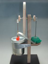
 A: The Frame
The frame is made out of plywood.
The vertical and smaller horizontal part is fitted together with a double groove to make the fit into an invisible connection.
When the double groove connection does not fit exactly, stability can be achieved by placing a small chock or a piece of profile strap on the bottom side.
The tin can holding strap takes care of disposing the energy at the cooling side of the cylinder.
Screw the parts together and use where necessary somewhat glue.
 B: The displacer cylinder and "piston"
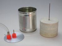
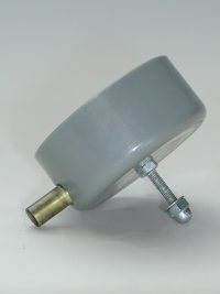
The cylinder is made of a tin can with a content of 30 cl. (soupcan)
If the tin can has a pull-lid, trim the remaining ridge off with a can-opener.
The displacer piston is made of balsawood.
Glue the balsawood planks crosswise together.
The manufacturing of the piston must be done accurately, ideally on a disc sander.
The air must be able to move freely around the displacer piston. The outer diameter must be approximately 3 mm smaller than the inner diameter of the tin can.
The height is about 25 mm smaller than the total depth of the tin can.
The lid rests on the brim.
The boring of the displacer gland must be purely perpendicular, so that the displacer piston can freely move without touching the inner side.
The flexible connection between piston rod and connecting rod is made of a smooth piece of cable mantel.
The cable mantel works as a hinge to divert the vertical motion into a radial motion.
Tape the lid tight on to the brim with elastic tape.
 C: The power cylinder and "diaphragm"
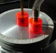
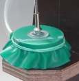
The cylinder is made of a pvc end-cap for pvc-tube 40 mm.
Try to find one with a rim, so that the rubber band will stay behind.
Glue the connection piece for the tube with epoxy glue.
The round diaphragm can be made of a piece of flexible thin rubber.
A piece of a latex or vinyl glove is sufficient, but is worn out very fast.
Remove the sharp edges at the diaphragm side of both flat washers. This will lengthen the usage of the diaphragm.
 D: The crankshaft with Flywheel
The small bearings must be fit without tolerance in the vertical support.
Also the crankshaft tube must fit without tolerance in the ball bearings.
Centre the threaded rod in the tube, if necessary turn some thin aluminium sheet around the threaded rod.
Glue the bearing pins on both sides with epoxy glue.
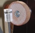
Place the flywheel as close as possible to the vertical support.
The flywheel must be an exactly round disk.
Remove as much as possible material in the direction of the centre (inertia).
Balance if necessary the disk with a nut in a fitting hole.
 E: The Heatsource
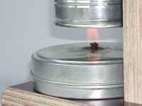
The heat source is a little spirit burner.
One or more wax-light candles are also sufficient.
The burner can easily be made of a flat lid box. A piece of a round cotton shoelace can be used as a fuse.
Use a little spirit and guard against fire risk!
Always turn off the burner when the engine is out of use.
- The measurement of power and revolutions
- The measuring of power and revolution is fully described on the site of Hugo Lindner.
You can also see a lot of beautiful engines in his gallery.
-For who wants more.............
- A model with prefabricated parts is for sale at Opitec : Art.nr 112.710
- Also a prefabricated model of the LTD-Coffee cup Stirling engine will come out shortly at Opitec. Art.nr ... ...
- Other models are described in extent in the following literature:

- Der Stirlingmotor einfach erklärt und leicht gebaut
Dieter Viebach
4e edition, 2002, Ökobuchverlag, Staufen
ISBN 3-922964-70-2

- Les Moteurs Stirling
15 plans
Rudy Mémin
1e edition 2004, J2P Editions, www.bateaumodele.com
ISBN 2-9518283-0-6
- Search:
Stirling engine, stirlingengine plans, Heissluftmotor, Stirlingmotor, Moteur Stirling, Hotair engine, Hot air engine, Moteur Stirling
Finally

|
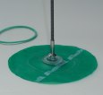
- Airtightness is important
- Minimal friction too


|
|


